Velodyne ULD15 Amplifier Repair
February 1, 2014
I bought a Velodyne ULD15 subwoofer in 1987. I helped my KEF 104/2 main speakers because they lacked low end response. Time passed and my inquisitive boys grew up. They were less inclined to stick their fingers through cone surrounds and the surrounds had deteriorated significantly.
I replaced the surrounds. I repair antique coin operated games like the Seeburg Shoot the Bear. Often the amplifiers only needed the electrolytic capacitors replaced to make them work again. I decided to do the same for the Velodyne subwoofer amplifier.
I butchered the job. There are a series of daughter cards perpendicular to the main board. I should have left them alone but I wanted access to the capacitors. I removed the boards and damaged some of the traces. I thought I repaired the damage and even checked my work.
The amplifier powered up the first several times without any problems. Then it popped and the magic escaped in the form of a small smoke cloud. I figured it was now beyond my capability and took it to a local repair person. He took one look, talked about the dreaded owner that pokes around inside, and suggested I purchase a used replacement. There were blown parts inside and he did not think it worth repairing.
I am compulsive about fixing things. Take a look at my website and the restoration work I do. I hate to just throw this subwoofer and amplifier away. Unfortunately I have no background in advanced electronics. I can handle relays and simple circuits. I do not understand solid state electronics. Well, that is an overstatement. I understand diodes, but not transistors. I started an online electronics course but I do not think I can learn enough to effect a repair.
Progress February 2014
I ordered new capacitors, a replacement for the blown chip, and new power transistors. I plan on adding a chip socket and replacing the power transistor in place. I have to figure out how to socket the daughter cards, raise them for access, repair them, and then replace them in the socket. I plan on only removing the comparator card in the hopes it is the only one with bad parts. The
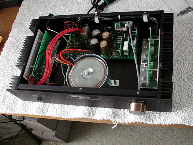
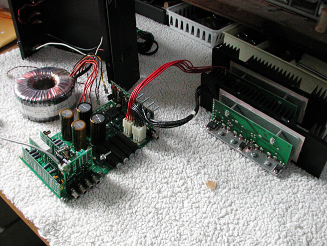
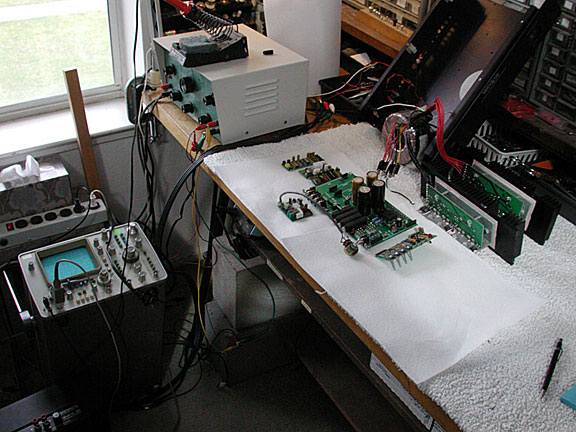
I have disassembled the unit and have it spread on the work bench. I have access to all the board, a couple of the daughter cards, and the power supply.
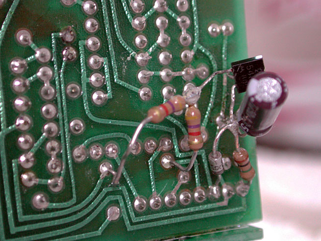
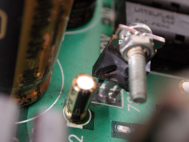
This is an example of some of the rework done on the daughter board. Note these components appear in the current schematic. I have also found a lot of traces that were cut, some repaired, some left cut. There was one trace that carried the preamp signal that was cut and the ground was also cut, with the signal now carried the length of the board using a twisted pair of wires. I imagine mine was an early board on the Series II schedule. 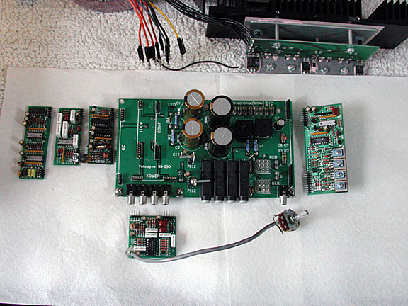
Progress March 2014
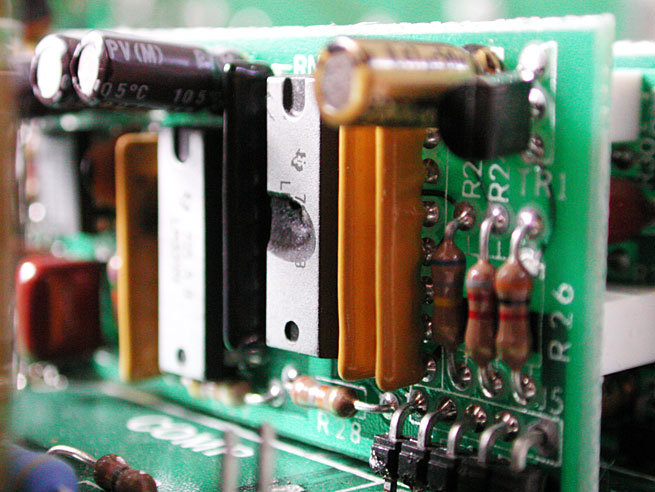
I removed all the cards from the main board and substituted header plugs, as shown above. The small boards, in order from left to right are Gain Compressor, Loop, Comparator, and Preamp. The board in front is the Crossover. I repaired the +12 volt power supply and the three chips on the comparator board that were blown when the 12 volt power supply let go. I fixed one of the rework transistor.
I have documented most of the signal all the way to the preamp board. However the turn on circuit on the comparator board does not appear to be getting all the signals it needs. I am not sure what the sequence of the turn on events is and I am not sure what values are supposed to exist before the bias is enabled on the amplifier.
I discovered the Gain Compressor schematic for the F series and found it very similar to the ULD15. I have added it to the documentation.
Progress March 2015
The amplifier and speaker have moved on to the next owner. They were replaced by a Rythmik Audio subwoofer.
Documentation
The documentation for the ULD15 is incomplete and some is very difficult if impossible to read.
The documentation is missing the schematic and board information for the gain compressor board.
The schematic for the comparitor board is difficult to read with much of the text illegible.
ULD15 schematics (includes loop board) updated March 7, 2014
ULD15 service manual (redone in pdf, some formatting changes, no schematics) updated March 7, 2014