Blackwatch Racing Key Fob
The stock elise comes with a key and integral light emitting diode to shine on the lock along with a disarm dongle to release the Cobra immobilizer. The Blackwatch Key Fob conversion combines the key and the Cobra transmitter into one unit. These steps show how to move the printed circuit board transmitter and key blank into the Blackwatch Racing case
It helps to have the key blank cut to fit the lock on your Elise prior to assembly. Make sure the locksmith knows what they are doing, locating the key blank correctly in relation to your original key. I was surprised when my regular locksmith refused to cut the new key and as a result, he will not get my business in the future.
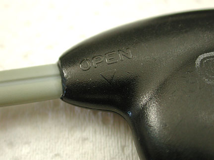
Remove the printed circuit board out of the Cobra transmitter fob. Look closely and you will see the "OPEN" and an arrow on the transmitter near the lanyard. Pry the case open at the seam where the small arrow is.
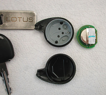
Remove the printed circuit board and battery.
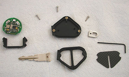
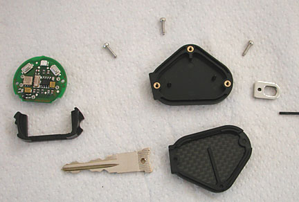
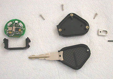
Examine all the parts of the new key and transmitter fob. Make sure there is sufficient clearance around the spacer so that the printed circuit board and all the components mounted on the board near the edge clear the spacer. Notice the spacer next to the printed circuit board
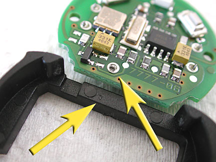
Notice the spacer already has a groove in it to clear a component on the left end. Mine needed additional clearance and while I was grinding an additional groove, I also leveled the spots used to cast the part. The bottom yellow arrow points to the place a component is pressing into the spacer and scratching it. I cut a groove in this area and smoothed the raised circles which are casting marks.
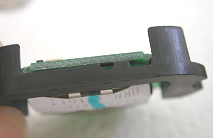
I checked the clearance. Notice the two grooves at the top of the spacer and between the spacer and the printed circuit board.
Place the buttons into the bottom part of the case.
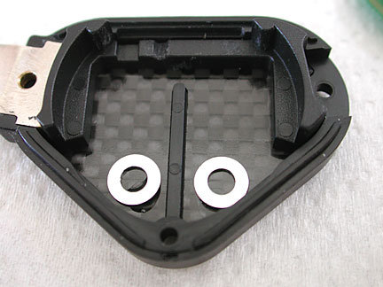
I did not like how far the buttons needed to be pressed because of the excessive travel. I added washers to the buttons to reduce the distance the button needed to be pressed before they contact the electrical switches indicated on the printed circuit board. (see below)
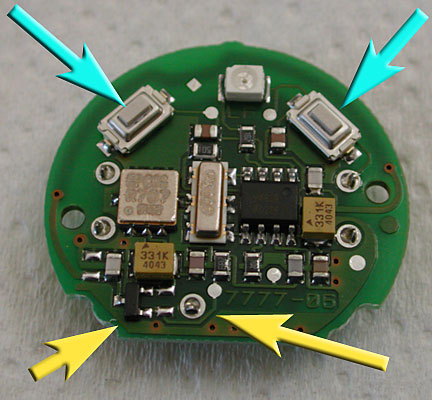
The yellow arrows indicate the raised components on the printed circuit board that needed clearance on the spacer.
The blue arrows point to the switches on the printed circuit board. The buttons need to press the switches in order to activate the transmitter.
Place the key blank into the bottom part of the case.
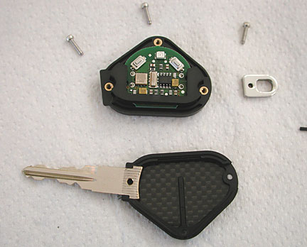
Add the printed circuit board and the spacer to the top part of the case. Make sure the pins in the top half locate into the holes in the printed circuit board. The spacer and printed circuit board should sit down inside the top case. (The spacer washers were added after this picture was taken.)
Carefully align the two halves of the case and press them together. Install the three hex head screws to hold the two halves together.
Comments
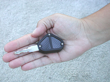
I prefer as small a package as possible for my keys. In fact, this is the only key I carry in my pocket. Notice I did not install the lanyard loop. I think the weight savings will make me slightly faster.
I wish the size of the case were a bit smaller. The fob is a bit thicker than it needs to be.
The red indicator light emitting diode does not have a hole through the case and does not shine.
These are small criticisms and should not prevent you from purchasing this modification.