Start Button Failure and Diagnosis
My 2008 Exige S 240 started having an unreliable start button. Multiple button pushes would not start the car.. The number of pushes increased from one or two, to over twenty and sometimes the car would not start at all. The car would start reliably by holding the start button down before turning the ignition key, but this also became unreliable. This all happened over a period of approximately 150 starts.
Researching the problem on LotusTalk.com and Seloc.org forums indicated others had similar problems. Several members had kludged solutions to bypass the start button, enabling them to start their cars. I got the impression, wrongly, that the problems started with the 2008 model year and this affected my diagnostic procedure.
This is the circuit diagram for the start button. The ignition turns on and provides power to the button (A), which in turn goes to the alarm/immobilizer (B). The immobiliser will not complete the circuit unless it has been disarmed by a button push on the key. Once the immobilizer has allowed the current to flow, the coil in the Engine Control Relay Unit (C) is energized, but only if the Engine Control Unit (E) provides a ground. Finally the coil closes the high current contacts in the Engine Control Relay Unit, which powers the solenoid relay in the starter (D). This solenoid relay provides very high current to the starter, causing it to crank. What could go wrong?
My first suspicion was the Immobiliser since it was new in 2008 and my assumption above was that the problem first showed up in 2008 and newer cars. I disassembled my dash. In doing so, the start button was removed from the left side above the cubby hole and so I checked it for continuity. It passed the continuity tester setting on my digital volt meter. Remember this, knowing the problem was intermittent and a switch is supposed to have two states, closed and open. It seemed to test correctly, closed when pushed.
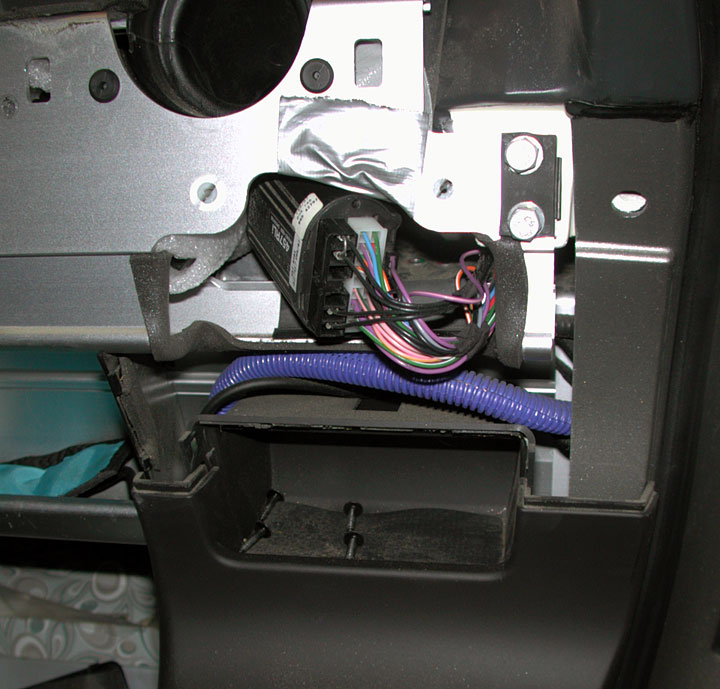
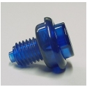
The immobiliser is located under the facia of the dash on the passenger side of the car. It is accessible through the hole of above the cubby. The immobiliser has a single machine screw holding it to the base of the dash and is also held in place by some double sided foam. The screw will be difficult to remove without removing the dash facia but it may be possible. Duct tape protects your hands from sharp edges. The purple/blue cable tube is not stock and routes wires for the aftermarket stereo.
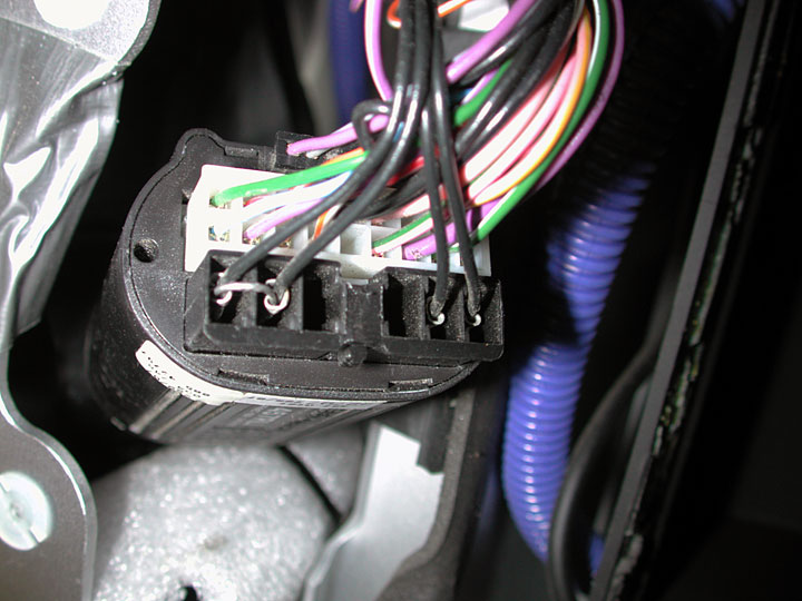
In order to remove the possibility of the immobiliser being at fault, I jumpered across the start circuit. The other two black wires energize the fuel pump. Documentation for the PFK 457 Alarm and Immobiliser. The car still did not start.
Others had problems with the Engine Control Relay Unit, also known as the Multifunction Relay Unit (MFRU), so this was my next component to check. On most 111 chassis cars like the Elise, the MFRU is located on the fire wall on the left side, near the Engine Control Unit. There is not enough room on the supercharged cars due to the tubes supplying cold air from the intercooler.
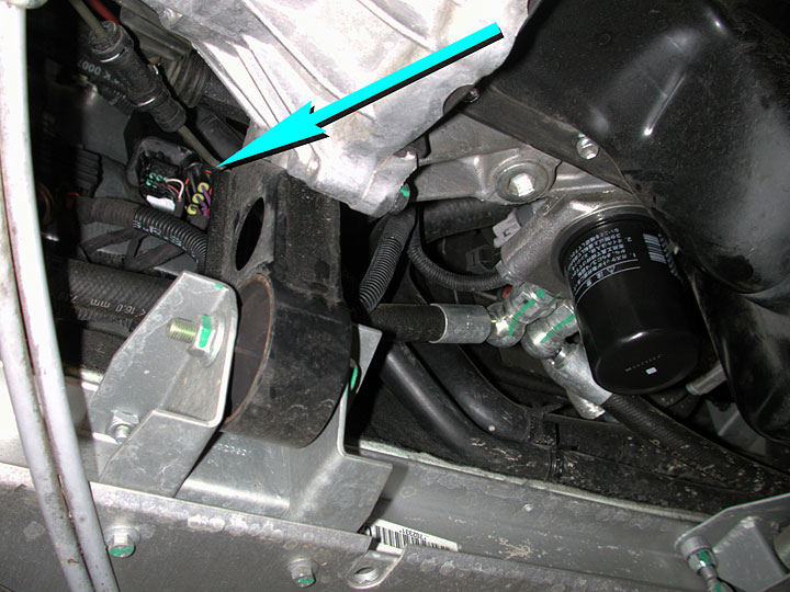
The Engine Control Relay Unit is accessed from the bottom of the car on the 2008 Lotus Exige, as indicated by the blue arrow. The box has a grooved back with a couple of plastic protrusions. There is a flat Z shaped bracket rivited to the fireway and the unit slides down over the bracket. Push up and slide a screwdriver in the middle of the bracket, between the bracket and the unit.
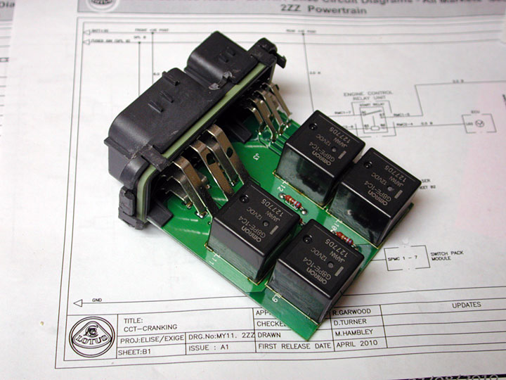
I could not think of an easy way to diagnose the start relay inside the unit. So I removed the cover and traced the circuits on the printed circuit board. In general there are four relays and each serves a separate purpose for the Engine Control Unit. Two are more connected but that does not affect the start relay which is number nine, closest in the picture, on the board. Once I determined the circuit for the number nine relay, I tested it using a 12 volt power supply. It worked when out of circuit.

This shows the pin outs for the Engine Control Relay Unit.
Several smart people from the forums suggested the problem might be the starter solenoid. Up until now I had avoided adding a wire with 12 volts to my diagnostic procedure, wanting to avoid shorting a circuit. I was not sure about the internal implementation of the ending ground provided by the ECU. So I ran a wire from the + terminal on the battery to RMC1-5 connector to the MFRU. This should energize the starter solenoid and it did. This is the first time I have heard the starter turn over in a couple of weeks! Removing the starter does not look easy and I was happy to find it was not the problem. Just to make sure the fault was not intermittent, I tried it several more times.
My next suspect was the ground on the ECU. Replacing the ECU is expensive and it is difficult to access. In order to test if the ECU was the failure, I removed the leg from the connector to the printed circuit board. On a through hole where that leg was attached, I added a short wire that I could attach to the chassis ground. This modification would make the ground for the starter relay permanent and reliable. I assume the start circuit is grounded by the ECU so it can control when the starter button push would energize the starter. The ECU knows the engine is already running and will not allow the starter to energize. The ECU knows the engine is not running and will then allow the starter to turn over. Testing this modified relay worked. At this point I was baffled.
I used the powered wire from the battery to go back up the circuit, first to the start relay since it was exposed, then to the immobiliser, which still had my jumper wire installed, all the way to the connector for the start switch. It all worked! Either the start switch was not getting any voltage from the ignition switch or the start switch was bad.
I removed the start switch and took it to the workbench to analyze. For a two state device it was acting very strange. I was able to get varying resistances from it, all the way from 360 ohms to mega ohms! Time to take the switch apart.
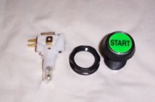
The switch is modular, separating the text on the button, the lighting, how it is mounted to the panel, the switch block, and an end cap. I was interested in the internals of the switch block.
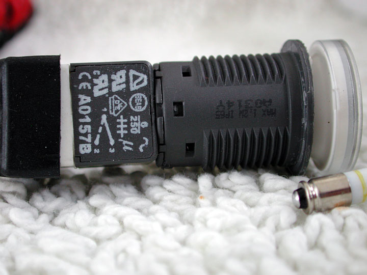
There is a cover, shown here with all the lettering on top of it. It is held in place by four plastic posts. Unfortunately the white stuff covers one edge. Gently prying up the other side allowed the cover to be removed but broke off one of the pins.
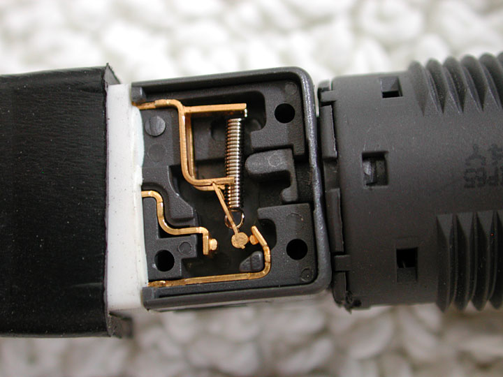
This shows the switch in the open position.
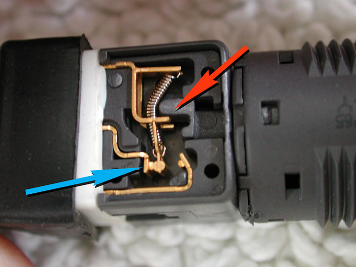
The button is connected to the plastic push pointed to by the red arrow. It overcenters the spring, which moves the cylinder, viewed from one end, to contact the output knife edge at the blue arrow. The cylinder should touch with its length on the knife edge. I examined it all and played with the alignment of the contacts. It all seemed to be working correctly and tested OK. I replaced the cap and tested again, finding it was again failing. It appeared the support for the sporing and the pivot point of the contact were standing proud of the edge of the casing. Putting the cap on only partially allowed the works to move freely and the unit tested OK.
This is my assumption. It appears that repeated button pushes bent the contacts and pivot point. Play in the mount points of the pivot and contact moved towards the cover plate of the switch. The cylinder binds on the side of the case, causing it to cock slightly as it rubs on the side. This prevents it from closing correctly or from closing at all!
I am not willing to spend $70 for a replacement start button that is prone to failure. It will soon fail again. A neighbor with a new Cobra 289 that he just finished suggested I use the start button from the Ford GT. Unfortunately they are no longer available and cost more than $100.. Some of you know I restore antique coin operated games like pinball machines. I suggest a flipper button is the perfect replacement, they generally cost less than $5, and they are absolutely reliable! You can find illuminated buttons and even buttons that say start!