Setting Up a Coon Hunt
This tutorial covers setting up your Coon Hunt and testing it to make sure it is working properly. Lubrication and maintenance are covered elsewhere.
Note: Do not use this method to setup a Coon Hunt that has not worked in some time. An old game with original oil and grease will not operate smootly and the motor, various gears, or the electronics will break and the cost of restoration will increase, sometimes significantly. Contact the Museum for suggestions on how to start an old game.
The Coon Hunt should arrive in three pieces, the main cabinet, a gun stand and gun.
Setting Up the Game:
- (If the gun is already wired to the gun stand, proceed to step 2.)
Attach the gun cable to the credit unit inside the gun stand. Lead the wires up through the smaller of the two holes in the bottom of the gun stand. The credit unit is the metal plate with relays and a motor, mounted inside the gun stand. The gun cable mounts to the terminal strip that is on the left side towards the front of the plate. See the schematic for which color mounts to which terminal.
If the colors are not similar, check the schematic delivered with the game or check for tags on the wire. Often a close color is substituted, for example yellow wire will substitute for the desired white. Make sure the player cannot pull the cable from the terminal. Use two cable ties or an automotive hose clamp to attach to the cable inside the cabinet to prevent it from being pulled through the hole.
- (If the main cable is already connected to the gun stand, proceed to step 3.)
Connect the seven wire main cable to the credit unit in the gun stand. Lead the end of the cable without the plug up through the big hole in the bottom of the gun stand. Attach the wires to the terminal strip at the rear, left of the credit unit. (Note: if your credit unit was originally from a Shoot the Bear, the terminal strip will be at the front on the right side. It is the only one with seven screw terminals.)
Check the schematic to determine which color goes on which terminal. It is not critical to restrain the cable like the gun cable as there is generally no movement of this cable.
- Place the cabinet and gun stand at least 20 feet away from each other, preferably 25 feet away. Try to position the gun stand so that no bright lights, such as bright windows, are behind the player.
- Lead the main cable up through the large hole in the bottom of the cabinet. Rotate the retaining plate across the hole and tighten the screw.
- Attach the plug to the amplifier in the tube socket on the right side of the amplifier. Note that two of the pins are larger than the other five and so the plug will fit in only one way. Make sure no portion of the cable is close to the mechanism.
- Route the main power cord through the hole in the bottom of the cabinet on the left side. Make sure no portion of the wire is close to the mechanism or motor and pulleys. Plug the power cord into a socket.
Note: The plug may have three prongs, including the ground prong. This does not mean the game is grounded and safe. This game was designed and constructed before grounds were required. It is strongly suggested that the game be plugged into a GFI (Ground Fault Interrupter) socket.
Note: Due to possible fire hazard, the game should be unplugged when not in use. The game can be plugged into a terminal strip and the strip turned off when the game is not in use.
- When closing the cabinet door, make sure no wires are swinging close to the moving mechanism. Check especially the whiner wires (red and green twisted) near the bottom right of the cabinet, and the score light cable, also at the bottom right of the cabinet. Check also the motor wire and plug, at the back left of the cabinet and plugging into the rear left of the amplifier.
- Turn the game on. The game is now ready to play.
Testing and Adjusting the Game:
Playing the game is the best way to test it. Small changes can be made to the sensitivity setting on the front of the amplifier. However, there are some adjustments that can be made before playing:
- Adjust the sensitivity knob on the front of the amplifier. In general, it should be in the middle, pointing at 12 o’clock. Rotating it to the right, clockwise, makes the game more sensitive. Rotating it counter-clockwise makes the game less sensitive.
- Setting the sensitivity to the minimum will help prevent false hits or hits caused by other light sources.Depending on the light in the room, light coming over the player’s shoulder, and how old the electronics are will determine where to adjust the sensitivity
- I suggest keeping the game as insensitive as possible and still register hits. The temptation is to think hits are being scored and ignored when a flash is seen on the lens in the side of the coon. Often these are the trailing portion of the flash, as the lamp inside the gun dims, and a hit was not actually scored. (The game only looks for the first portion of the flash, as if a bullet were fired from a gun.)
- Inside the gun stand, there are three lamps connected in series with the lamp in the gun itself. They are connected to the terminal that connects to the gun cable. These lamps attempt to reduce the voltage to the lamp in the gun, thus protecting it and giving it a longer life. (The gun lamps have become very rare and are no longer being made.)
If the gun is not registering hits, these lamps can be removed one at a time until satisfactory game play is reached. If the game is not registering hits, remove one of the lamps. Play the game for a while and if it is still not playing satisfactorily, remove another lamp. The game will play as designed if all three lamps are removed. (The assembly is held on only by the terminal screws and a tie wrap and can be removed easily.)
- The game can be tested easily without having to shoot at the moving targets by turning off the motor when playing. With the motor stopped, the coons will not be moving and make for easy targets. This can also help diagnose other problems such as if the amplifier is working, if the sensitivity is set correctly, and if the rails are dirty.
Dirt on the rails can cause false hits so that even when the gun is pointing at the ground and the trigger is pulled, a hit is detected. When the coon is not moving, this should not happen.
- It is possible that the coon will not detect a hit because the contacts are sitting on a dirty patch on the rails. Try moving the coon carriage and shooting at the stationary target again.
- Check the focus of the gun lamp by firing at a dark spot on the wall. The spot should be a circle about one inch in diameter and should be round. The rough handling of the gun can cause the lamp to go out of alignment. See instructions for aiming the lamp in the manual.
Problems:
Left coon making the right Coon's whine:
It is not uncommon for the left coon to make the sound of the right coon when hit. This is because the whiner, the sound generator, always makes the sound of the left coon unless a switch connected to the right coon is closed. The switch is closed all the time the right coon is traveling behind the tree. As a result of the design, the left coon will make the incorrect sound while the right coon is behind the tree.
This is inherant in the design. The whiner was an option and was not installed in all the games. As a result, the factory did not add complexity by connecting the whiner to each coon. Rather they connected it to the right coon and only change the sound when the right coon is behind the tree.
One coon acting dead when shooting at the other coon:
Sometimes the coon not being shot will act like the coon that is being shot. Cross talk happens when the right or left coon is aimed at and hit, but the other coon acts as if it were hit. Actually, a coon can act as if it were hit even when the gun is pointing elsewhere. Voltage spikes inside the amplifier cause all of these anomalies. These spikes travel through the wires and occasionally get amplified and sent to the relays. The result is a hit when none is desired. When one coon is hit, a very large spike is created to trigger the hit and this puts a load on the power supply. Since both coons share the same power, a load on it can give the same appearance of a hit as a light pulse. Reducing the sensitivity as much as possible can minimize this effect.
Dirt on the rails, missed shots, acting dead when not shot:
Dirt on the rails can also cause false hits. The game does not pay attention to light pulses except for the instant the trigger is pulled. However, if the gun is aimed at the floor and the trigger is pulled, the amplifier will look for sudden current signaling a hit. Dirt will interrupt the small current going to the photocell and reconnecting the contact on the rail after the dirt will appear as the desired light pulse.
Cleaning the contact rails:
Keeping the rails clean will not prevent this problem but will minimize it. I suggest using 3M abrasive pads to clean the rails. These are not actually steel wool. Do not use steel wool as it will leave bits of metal in the works, which is bad. Put a rag at the bottom to protect the works from any debris that might fall while cleaning or working on the coon carriages.
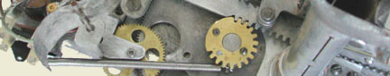
Adjusting the End of Game cam
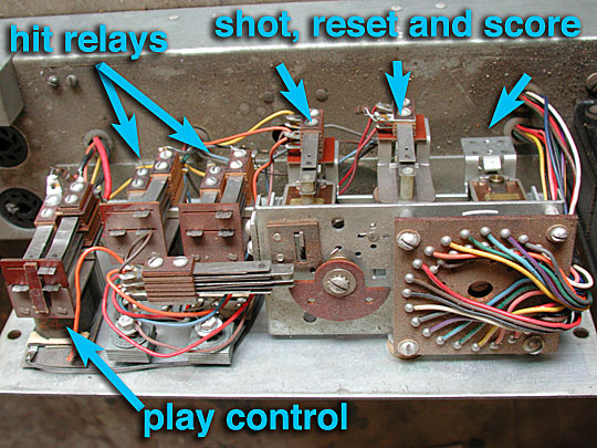
The switch stack is activated by the half circle cam. The shots are recorded by the shot relay on the other side that rotates the half circle cam one click (shot) at a time. The cam is shown in the reset or beginning of the game position.
The switch stack consists of three switches. The one on the bottom is normally open. The two on the top are normally closed. The two on the top do not get opened until the cam has rotated 20 clicks, about 180 degrees. The curved portion of the cam will be on the top at the end of the game.
If the top switches are out of adjustment, the game will often continue playing beyond the 20 shots. This is because the final click of the relay is never completed. The relay will attempt to rotate the cam one final click but the power will be interrupted and the full stroke of the relay will not complete. This is because the switch is opening too soon and causing the power to pull from the relay before it has finished the stroke.
Here is how I adjust the leafs of the switch. The leafs are numbered from top to bottom, 1, 2 for the first contact and 3, and 4 for the second. Notice leaf 2 will push open by pushing on leaf 4. These two are labeled J and K in K2, the shot stepper in the schematic.
- click the shot relay 20 times so the cam is in the end-of-game position.
- both switches need to be barely open
- make sure leaf 2 is being depressed by the cam. Pushing the reset (middle) lever and allowing the cam to go to the reset position should allow leaf 2 to raise to contact leaf 1.
- make sure leaf 4 is being depressed by the Nylon block on leaf 2.
- adjust leaf 3 so it is very close to leaf 4 but not touching when the cam is in the game over position.
- adjust leaf 1 so it is very close to leaf 2 but not touching when the cam is in the game over position.
It is critical that the leafs of 1 and 2 do not open until the shot count relay has moved past the 20th click of the shot count wheel. Another way to say this is that the contact should not open until the very last portion of the stroke of the relay.
What happens is the following: the replay starts its stroke and gets past the ratchet on the shot count wheel when the contacts open. Opening the contacts causes the power to be pulled from the game and the play control relay to open, ending the game.
If the contacts of leafs 1 and 2 open before the relay pulls the past the 20th click, the power will stop, the relay will not fully increment the end of game came, and the cam will bounce back to the 19th click.
My apologies for the dirty mechanism.
This game has not been restored.
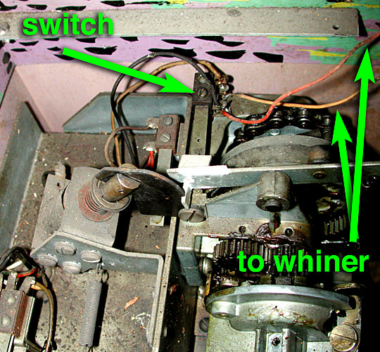
Whiner Switch Adjustment
Examine the wires coming down the right side of the cabinet from the whiner. They lead to a two contact switch stack that is activated by the right top planetary gear. The gear is activated by the solenoid shown above. When the solenoid pulls in, it releases the planetary lever which lifts up. As it lifts it closes the two switches.
According to the whiner installation manual:
E. Adjust the blades of this new Turn Switch so that the contacts have a gap of 1/32 of an inch minimum, (and 40 grams of pressure) with the lever unlatched.
Note: The left coon will make the right coon sound whenever this switch is closed. This switch will be closed whenever the right coon is descending. Unfortunately because of the design, it is normal for the left coon to make the right coon noise when the right coon is descending.