
Sous Vide Wiring Diagram
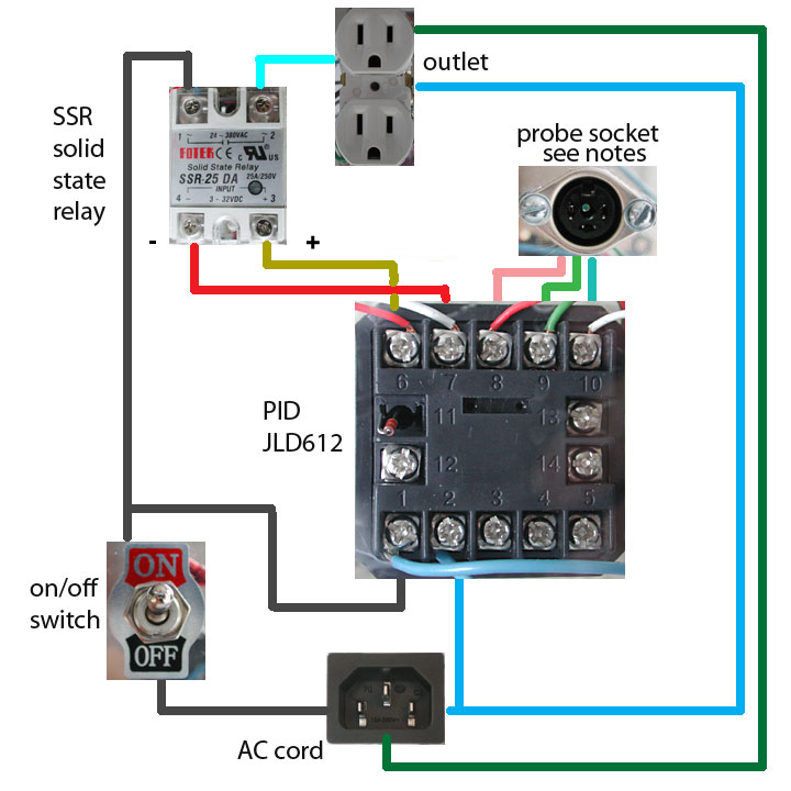
Here is the wiring diagram for my sous vide controller. Please read the notes below with regard to the temperature probe wiring and the ground wire. Note, I do not warrant the diagram is correct and you should exercise caution when playing with electricity. Use at your own risk. ( I apologize for the disclaimer. )
Notes:
- The ground wire, in green originating at the AC cord socket, is brought up to the outlet. An alternative is to use a ground fault interrupter outlet. My kitchen already has these in place and so I decided I did not need the redundant protection.
- The wiring of the temperature probe needs some experimentation. Mine did not work as described. The PID suggests that terminals 9 and 10 are common and terminal 8 is the center wire. I wired the PID outside of the box and tested the probe before finishing the wiring. There are only three wires, two colored the same. No harm will come to the probe if the wiring is not correct, so you can try the combinations to determine the correct. You will see the ambient temperature appear when you turn on the power and the probe is wired correctly. If you use the same components that I did and have additional information about what works, please let me know and I will correct this note.
- I used the SSR (solid state relay) 25 amp model. The PID will switch the current on and off every few seconds. A contact relay could be used instead of the SSR but will be constantly clicking. This is quiet and more reliable.
- I used the PID JLD612 model. There are several alternatives that can be used and the wiring will be similar.
- Please contact me if you have any suggestions on how to make this better. I am not an electrician and I possible have made some bad assumptions.