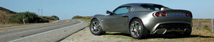
Suspension from Lotus Elise and Exige
Lotus Cars: Shop Manual: Lotus Elise Front Suspension
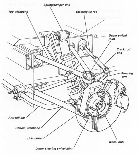
Front Suspension
The fully independent front suspension comprises, on each side of the car, upper and lower, fabricated tubular steel wishbones, with a concentric coil spring/telescopic damper unit picking up on the outboard end of the lower wishbone. An extruded aluminiurn alloy hub carrier, houses a dual taper roller bearing which supports a steel hub equipped with 4 wheel studs. A forward mounted tubular steel anti-roll bar, is supported in plastic bushes and is operated via short ball jointed drop links from the lower wishbones.
The inboard ends of both wishbones use replaceable bonded rubber pivot bushes to provide maintenance free articulation and suppression of noise and vibration. Both upper and lower steering swivel ball joints are pressed into housings incorporated into the outer ends of the upper and lower wishbones. The upper ball pin is secured to the forged steel, rearward facing steering arm, itself fixed to the hub carrier by two M1 0 bolts. The ball pin of the steering lower swivel joint is secured in a forged steel plinth bolted to the bottom of the hub carrier by four M10 setscrews. The spring/damper unit acts between the outer end of the lower wishbone and the chassis front crossmember, and is fitted with the damper rod lowermost in order to minimise unsprung weight.
In order to protect the alloy hub carrier from the effects of electrolytic corrosion, it is important to ensure that the joint faces with any steel components are coated with the specified jointing compound before assembly.
Modifications
to be added?
Lotus Cars: Shop Manual: Lotus Elise Rear Suspension
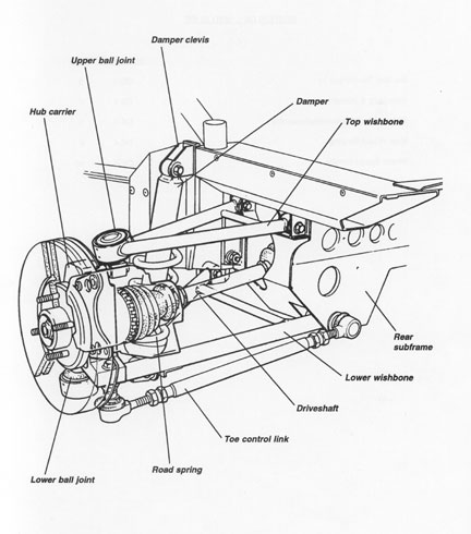
Rear Suspension
The fully independent rear suspension comprises, on each side of the car, upper and lower tubular steel wishbones, a toe control link, and a concentric coil spring/telescopic damper unit picking up on the outboard end of the lower wishbone. An extruded aluminium alloy hub carrier, houses a dual taper roller bearing which supports the outboard driveshaft and a steel hub equipped with 4 wheel studs. Onto the LH hub carrier is mounted a wheel speed sensor which operates in conjunction with a sensor ring on the outboard driveshaft, in order to supply vehicle speed signal to the speedometer.
The inboard ends of the upper and lower wishbones use replaceable bonded rubber pivot bushes to provide maintenance free articulation and suppression of noise and vibration. The two legs of the rearward biased top wishbone, pick up on the chassis rear subframe, and converge outboard to a ball joint housing into which is pressed a ball swivel joint. The ball pin of this joint locates in a forged steel plinth which is itself secured to the hub carrier using two horizontally disposed M1 0 bolts. The braced, wide based, forward biased lower wishbone, is anchored at its front inboard end to the chassis rear crossmember via a steel bracket, and at its rear inboard end to the rear subframe. The outboard end of the wishbone houses another swivel ball joint fixed via a forged steel plinth (similar to that used on the front suspension) to the bottom of the hub carrier by four bolts.
The adjustable length, double ball jointed toe control link, shares a chassis anchorage with the rear of the lower wishbone, and picks up on a rearward extension of the hub carrier.
The spring/damper unit is fitted with the damper rod lowermost to minimise unsprung weight, and acts between the outer end of the lower wishbone and a steel clevis bracket bolted to the rear end of the chassis main side rail.
Certain components are common with the front suspension, and include: top and bottom swivel joints, hubs and hub bearings, and some wishbone pivot bushes.
Modifications
(to be added)