Contents:
Introduction
Play
General Description, Components
How It Works
History
Restoration Part 1
Restoration Part 2
Restoration Part 2
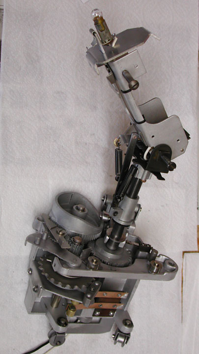
This is a bear carriage without the bear form. the two contacts at the bottom carry the signal from the light sensor and the light power when the eyes and mouth light up. The cam is the sloped cylinder at the top left of the carriage and causes the bear to raise and lower when it gets hit. The pivot points for the legs are the screws sticking out of the black portion of the carriage as it supports the actual bear.
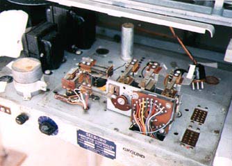
Rebuilding console
The console was more complicated than I first expected! I expected a couple of simple coin slides. The cabinet contained the coin motor that controls the logic for how many plays for each coin and there is circuitry that controls the light in the gun. I recorded the serial numbers and other notations inside the cabinet. To the upper right of the coin box was the number 7228. On the right angle axle support:
Rail and Target Assembly, Type RTA 1 L6.
J. P. Seeburg Corp SER 3486
Chicago
On the back of the instruction plate, written by hand, "4682 Gun Stand".
I searched all the electrical supply houses for the five conductor wire of the correct gauge. It needed to be neoprene coated and flexible enough to allow for movement of the rifle, but the wire needs to be heavy enough, 22 gauge, to carry the required current with little resistance. I finally found some but had to buy ten times the amount required. Searching the Internet for wire suppliers helped, but it was difficult to find the right wire.
The coin unit is complicated. It consists of a pinwheel that has movable tabs or vanes. Depending on which coin the player puts into the coin slide, a solenoid bends a particular vane. As each credit is used, the credit motor rotates the vanes around one position. When the bent vane finally reaches the top, it is bent back to the original position and no further credits are available. The ultrasonic cleaner was perfect for cleaning this component.
Rifle and Light
The rifle stock had been refinished long ago and was nicely worn. I left it as it was. The barrel was obviously repainted black. I do not think this was original but since I did not know what it was originally, I left it alone. I also knew all the light going down the inside of the barrel needed to get to the other end. The black paint and dirt absorbs the light so I tried to polish the inside as much as possible. I rebuilt the trigger mechanism and adjusted the spring tension. The trigger pulls a normally closed switch open and closes another to trigger the light.
The light found in the holder was burnt out. I was able to find two replacements, one manufactured in Japan for a quarter the price of the replacement General Electric lamp. I bought five of the Japanese versions, figuring I should be able to get it to work, perhaps burning out one or two, and then retain the others as spares. Boy was I wrong. The problem was difficult and I quickly burned out the first five. I ordered five more before I got the game working.
The light bulb is contained in a metal socket, which is connected to a casting locating the bulb holder to the end of the rifle barrel. There are four alignment screws that help aim the light within the casting. The casting has a tiny hole and the filament of the bulb needs to be precisely aimed through that hole. The screws for the alignment fixture were broken off and needed to be removed. The casting is never really attached to the gun barrel but rather fits in the end and then is compressed with a rubber pad inside the stock of the gun. This provides some shock mounting to preserve the lamp. The alignment needed to be exact in order to shine a round spot so far away.
I created a light table on my workbench and ran into my biggest problem. I tried to fire the gun and see the light flash in order to align the lamp. The filament burned out immediately. I replaced the lamp and examined the supply voltage. The supply was 13 volts for a lamp that is supposed to take six volts! How could that be? It was correct and even showed the lamp supply to be 13 volts on the schematic.
I then spent three months researching the properties of a lamp, especially when it is being supplied with too much electricity, even for an instant. I asked the question on the Web, on rec.electronics.repair. Mark Kinsler was kind enough to take the time to understand the problem and provide helpful diagnostic hints. I also found a doctoral thesis on the effect of electricity on the lamp filaments and ordered a copy. Obviously it was written using pure physics to describe the effects and was difficult to understand. It did hint at thermal shock of the filament being the main problem and helped me understand the need for a small current to keep the filament hot, preventing the sudden expansion due to heat. By preparing the filament, the designers expected the filament to survive for an instant.
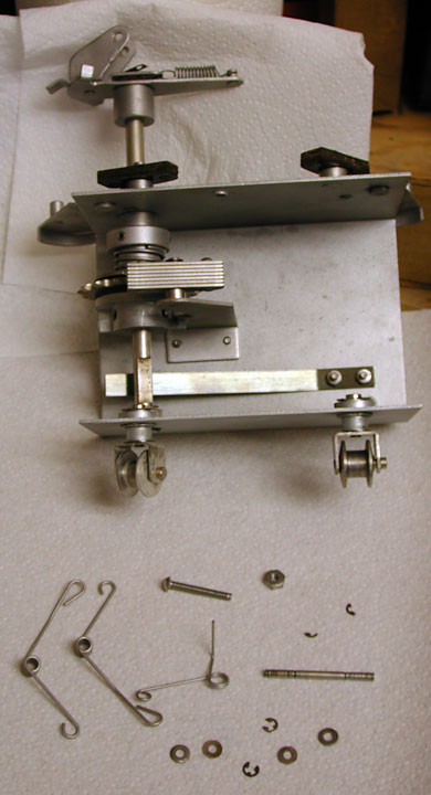
This is what the dog carriage looks like without the dog. The spings will allow the dog to appear to be running as they trip on the springs sticking out from the track. The metal strap just above the bottom wheels keeps the dog pointing in the right direction after a turn as it rests on a flat on the pivot axle.
On more careful examination, I found this was by design. The lamp is supplied with a small current, just enough to make the filament glow. There is also a wire wound resister available to adjust how long the lamp stays lit during a shot. While waiting for the player to shoot, a large capacitor is charging. This is then discharged into a relay, thus causing the 13 volts to light the lamp. The wire wound resister allows some of the current to by pass the relay. I mistakenly had adjusted it so all the current would pass through the lamp relay, causing the lamp to stay lit for much too long. Putting it at the other end of the adjustment scale allowed me to fire the lamp for one shot and survive. One difficult problem solved!
I also ordered a General Electric replacement lamp, #1489, and found it could handle the additional voltage better than the Japanese replacements.
I still needed to align the lamp! Since it fired for only an instant when the trigger was pulled, I spent a lot of time just hunting for the dot. I put a couple of #44 lamps in series with the gun lamp so the lamp could stay on for an extended time and darkened the room. I then jumpered the shot relay closed, causing the lamp to stay lit. The adjustment of the casting, and the position of the lamp in the holder is extremely critical to getting a good spot of light 25 feet away. I was able to align the gun finally!
I left one of the #44 lamps in series with the gun lamp to further safe guard the filament of the gun lamp. It seems to work just fine.
Update
The lamp holder is attached to the lens holder and assembly with two screws. These screws pass though the lamp holder and are not threaded in the lamp holder but are threaded into the lens holder and pull the lamp holder to the lens holder. There are two other screws that are threaded in the two other holds in the lamp holder, 90 degress from the screws described above, that push the lamp holder away from the lens holder. When adjusted properly, they push the lamp holder away from the lens holder about 3mm or 1/8 of an inch.
I use three #44 lamps as a way of protecting the 1489 lamp. I put them in parallel(!) which drops the voltage slightly. I use this during the operation of the game. I suggest to the customer that they try the game with three #44s plugged in. If it does not play acceptably and hits are not detected, unplug one of the #44s at a time. Hopefully it will play correctly before all are unplugged. The 1489s have gotten so expensive and hard to find that I try to protect them.
The #44s are not used when I focus the gun lamp. Instead I supply the gun lamp with a six volt power, which causes it to glow brightly. Be careful because the holder will get very hot.
Here is how I focus the gun:
- I remove the cartridge from the gun. The cartridge holds the 1489 lamp and a tiny lens. The lamp holder itself has two threaded holds and two open holds for #2 screws. Two of the screws pass through the open holes and are threaded into the cartridge. These two screws are 180 degrees from each other around the circumference of the lamp holder. These two screws hold the lamp holder to the cartridge.
- There are two threaded holes on the lamp holder, 90 degrees from the holes mentioned above. Thread #2 screws through these holds. These screws push away from the cartridge.
- This arrangement allows two of the screws to push and two to pull. In this way the lamp holder can be mounted away from the cartridge about 1/8 inch and can be tilted in any direction to focus the beam of light.
- Next I connect the gun lamp to a six volt power supply. I actually use a bit less than six volts because the lamp gets hot quickly and heats up the lamp holder, making it difficult to adjust the screws. I focus the light coming through the lens on a white piece of paper about 12 inches away from the cartridge. Try to have the image directly in line with the cartridge.
- A question I have is what part of the image should be in focus. I can actually focus a portion of the filament of the lamp in the image! I wonder if this is the way to get most of the light from the apparatus, when all is assembled? Ideally, the image of the filament should be focused at approximately 19 inches, the distance to the lens at the end of the barrel.
- Once the preliminary focusing is done, I attach the cartridge to the gun barrel. Older designs had a couple of fingers on the barrel that grabbed the cartridge and a pin on the bottom of the cartridge to locate it to the barrel. Newer designs left the fingers off and relied on a rubber pad to keep the cartridge close to the end of the barrel. This probably lessened the shock to the lamp when the players bashed the gun into the gun stand or other objects.
- Now I focus the light at a target about 20-30 feet away. The spot of light should be round and evenly lit, and should be about the size of a quarter. If the spot appears to be a portion of the moon, like half lit, then the #2 screws can be adjusted slightly. Tighten the screw that corresponds to the darkened portion of the spot. This is the screw that is threaded into the lamp holder. Loosen the screws that are pushing away from the lamp holder on either side of the screw that you are tightening. Usually, if you pre-focus the cartridge, there is little adjustment required here.
- I believe the light emitted from the filament coil of the lamp travels through the first lens where the first lens focuses the filament light on a one inch spot 19 inches from the cartridge. The second lens, located there, gathers that light and turns it into a column of light that does not expand but travels 20-30 feet and stays about the same size. I considered polishing the inside of the barrel, thinking to reflect more of the light. However I think that will just scatter and cause a less distinct dot at the target.
- Make sure the rubber pad locates the cartridge against the gun barrel when you are assembling the gun.
- The timing of the light flash is important not only to make the spot of light bright, but also for the electronics. I use an oscilloscope to time the flash to 0.10 second. Making the flash too long will allow the player to track the target and get a hit more easily, almost as if playing with a machine gun. On the other hand, a too short pulse will not be detected reliably. It is better to gain reliability by adjusting the sensitivity.
Many customers expect the game to play with 100% reliability, with every close shot scoring a hit. They can see the flash of light in the lens of the target on the bear or coon. This is not a computer and the technology used has some flexibility. Even more important, the circuitry only detects a hit at the start of the pulse! So while the player might track across the target, and the light spot hit the lens, it only counts if the light hits the lens right at the start of the shot.
I can imagine groups of kids hanging out in the arcade. One of the boys is showing off to his girl friend, or better, one of the girls is showing up the boys. They have practiced and have learned the response of a particular game and how it is set up. Once learned, it is possible to get 20 hits out of 20 shots. Difficult, but still possible. I have been able to time a shot, aimed at the ground, to coincide with the exact instant the bear emerges from the forest. The light from behind the shooter will strike the photocell at that instant, appearing to be the light from the gun. It scores the same as a hit.
When setting up the game in a location, I turn the motor off on the target. I can then shoot at a stationary target and test to see if I can get 20 hits for 20 shots. If I can, then the game is ready to be played. Occasionally I will find the contact track has oxidized and is not making reliable contact. I use non-metallic steel wool, the 3M pads, to clean off the oxidation and then spray the rails with contact cleaner that contains silicons and a Teflon lubricant. While I have no direct evidence that it helps, my hope is that the lubricating properties will prevent rapid oxidation.
Assembling and Testing
It was time to put the whole thing together and try it out. I put the track into the cabinet and placed the bear on the track. I put the amplifier under the track and connected the wires to the track, the gun console, and the rifle. I turned it on. It did not accept coins.
The coin slide mechanism pushes and then pulls a regular switch. The switch closed one set of contacts during the coin sliding, but opened another set to the coin motor to prevent multiple slides per coin. One of these anti-cheat switches was bad so the motor would not run, establishing the first credit. I replaced the switch and things seemed to work.
Now the coins are accepted and the bear runs around. However shots were not detected. I contacted another GameRoom magazine contributor and advertiser, Bill Bickers. He writes helpful articles on jukeboxes and offered to help readers with jukebox problems. I figured this was a Seeburg, a jukebox manufacturer, so I gave him a call. He was very helpful and led me to a soldering problem on one of the tube sockets.
It finally works! I was so excited about the bear running around, I missed every single shot! My children heard the mechanical racket and came running, demanding their turn. That poor bear did not know which way to turn!
Some minor adjustments were still necessary. The shot count missed from time to time, so I adjusted the count wheel. The light in the bear's head did not shine when the bear was hit, but a quick check showed a loose wire. Finally, the trigger seemed to stick when little fingers held it close to the trigger guard. A quick mechanical adjustment and it felt just right. The game has provided many a happy hour of entertainment ever since.
There are more adjustments that affect the way the game is played and the sounds it makes. For example, the ratchets that hold the bear in place on the track while it turns can be adjusted to make little noise. The adjustments on the amplifier and gun stand can affect how often you will have false hits or even misses. All this fine tuning is beyond the scope of this restoration article. Many of the techniques have been learned as I restore more and more of these games and are complicated to imlement and even more comlicated to explain.