
Installing New Turbo Intake Manifold
Installation Instructions
There are several benefits to a cold air intake especially if it is well designed. The flow of air into the engine experiences little resistance. The air is cold and more dense, thus increasing the amount of air and fuel. There is potentially some benefit to increasing the density of the charge because of sound waves going back and forth as well.
A potential problem with an intake is the increase in induction noise.
The TurboXS Cold Air Intake is easy to install.
You can download and print the instructions in pdf format or get a print version of these instructions.
Inventory
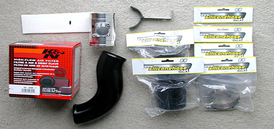
The above picture shows the list of components:
- K&N air filter (RX-3900-1)
- mass air flow sensor mount (polished tube with mount)
- sensor to air cleaner pipe (curved black tube)
- pipe support (L bracket with U support)
- nipple cap (small black cap on white stickers)
- two silicon hose connectors
- four hose clamps
- mandatory stickers!
Lotus Manual on Mass Air Flow and Air Temperature Sensor
The stock parts that need to be replaced are the air snorkel, air filter, and the mass air flow body and sensor. These parts are located in the upper left portion of the engine compartment. The air snorkel and air filter are located just behind the air intake grille in front of the left wheel. They are most easily accessed through the left wheel well. Interestingly enough, it was difficult to find, including the mass air flow pipe and sensor in either the Lotus or the Toyota manuals.
Removing Existing Parts
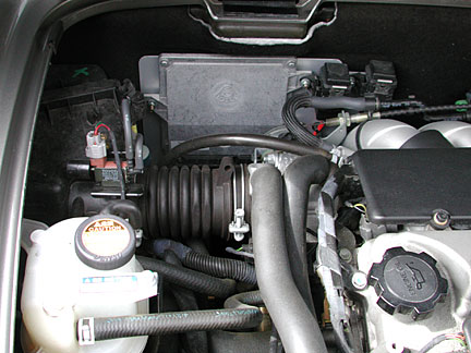
The intake is shown above. It is the ribbed rubber tube and the wire clamp that attaches it to the throttle body and intake of the engine. To the left of the ribbed tube is the air filter housing.
Tools
- flat blade screwdriver
- Philips screwdriver
- 13mm socket and wrench
- 10mm socket
- Allen wrench?
- lug wrench
- car jack
Process
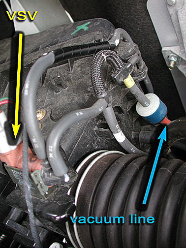
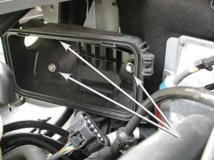
- remove the electrical connector to the VSV (airbox flap valve vacuum switch), pointed to by the yellow (left) arrow. The plug has a tab that must be depressed to remove the connector.
- remove the vacuum line connected to the anti-backfire valve, pointed to by the green (right) arrow, from the intake on the engine. Plug the vacuum nipple with the rubber cap provided in the kit.
- loosen the wire band that holds the rubber tube to the throttle body on the engine. (See picture of engine compartment shown above, wire clamp is on the ribbed rubber tube, on the right hand side of the tube.)
- using the center jacking point A and remove the wheel and tire.
- remove the wheel well liner. To remove, unscrew and remove the Philips head screws and pull the plastic liner from the mounting point. The expanded fastener will pop loose. There are six fasteners including one under the frame.
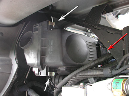
- open the clips on the air filter housing and remove the air filter
- rotate the air filter housing and intake tube to get access to the mass air flow sensor plug. Remove the plug by depressing the tab on the connector.
- disconnect the vacuum line from the engine intake. Remove the line that leads to the back flow valve, a one inch cylinder. Plug the nipple on the back flow valve.
- tie back the vacuum line making sure to keep it from the throttle sector that rotates near the throttle body.
- extract the air filter cover out of the engine compartment or through the wheel opening.
- remove the three 13mm hex head bolts that mount the air filter box and remove it as well.
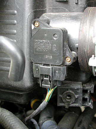
- remove the mass air flow sensor from the stock intake by removing the two brass colored Philips head screws. These screws may have machine M4 threads and can be reused.
Note carefully the orientation of the sensor as shown below, especially at the end where the air flows through the hole. The small end (hole) with plastic buttresses points to the source of air and the air filter. The big end (hole) points to the throttle body and the engine. The lettering on the top of the sensor as shown in the picture above reads from left to right and the air should pass over the sensor from left to right. The air temperature sensor is at the base and to the right of the mass air flow sensor "tower" as viewed from the path of the incoming air. The direction the air passes over the sensor is critical and will need to be the same when the sensor is mounted in the new intake.
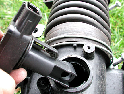
intake or air filter side
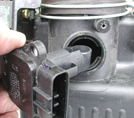
output or throttle body side
continue to add new intake